Ball-Balancing Parallel Robot (3-RRS)
Solo project, Jan–May 2026. A 3-DOF parallel robot that keeps a rolling ball centered on its platform using a camera, inverse kinematics, and PID control. I designed it in SolidWorks, built it, and wrote the controls in Python on a Raspberry Pi.
Once it settles, it holds the ball within about ±10 mm of center. The camera tracks the ball at 30 frames per second, and the control loop runs at 100 Hz.
Controls
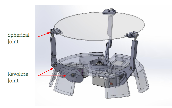
Developed an inverse-kinematics model using vector geometry and linear algebra to convert a commanded platform pose—defined by position and surface normal vector—into the corresponding servo motor angles.
Implemented a 30 FPS computer-vision pipeline on the Raspberry Pi using Gaussian filtering, morphological erosion/dilation, thresholding, and contour detection to isolate the ball and calculate its pixel-space centroid in real time.
Converted the measured ball centroid into a position error relative to the platform center, providing continuous feedback to the closed-loop controller.
Implemented and tuned a PID controller using proportional, integral, and derivative error terms to generate platform tilt commands, balancing responsiveness against overshoot, oscillation, and steady-state error.
Integrated the vision, control, and inverse-kinematics calculations into a 100 Hz real-time feedback loop, continuously updating servo commands as the ball moved across the platform.
Generated servo position commands through the Adafruit servo controller, translating calculated joint angles into PWM signals for platform actuation.
What went wrong first
My first attempt integrated everything at once: vision, IK, and PID, planning to tune out whatever problems remained. The ball oscillated or rolled straight off. I kept treating it as a PID-tuning problem until I broke the system apart and saw that camera latency, calibration error, platform response, and the controller were all interacting.
I rebuilt it bottom-up:
Validated the inverse kinematics on its own.
Tested platform response on one axis, then two.
Simplified the vision pipeline to filtering and contour detection.
Changed the first goal from aggressive tracking to reliably holding the ball at center.
Once each piece worked alone, I reintegrated them and the robot balanced the ball to within ±10 mm.
Lesson: characterize the subsystems before tuning an integrated system.
Hardware
Raspberry Pi 4B — executes image processing, PID control, inverse-kinematics calculations, and real-time system coordination.
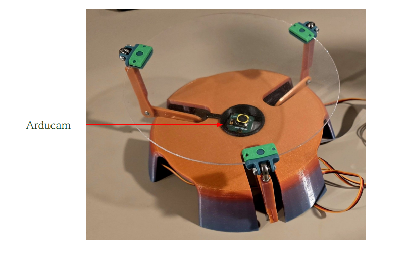
Arducam 3 — captures the platform workspace for high-frame-rate ball position tracking.
Adafruit Servo Control Board — generates PWM control signals for the platform’s servo actuators.
Servo-actuated balancing platform — mechanically converts individual servo rotations into controlled changes in platform orientation.