FSAE Motor Cooling: Thermal Model & Jacket Testing
Hytech Racing, Georgia Tech's electric Formula SAE team (3rd place, FSAE Michigan EV). Aug 2024 – Dec 2025. I built the transient thermal model of the motor and accumulator cooling loops and ran the experiments that validated it.
By the end, the model's error against our test data was about 20% lower than the team's previous model, and the jacket tests it guided led us to a design geometry that was 15% more efficient.
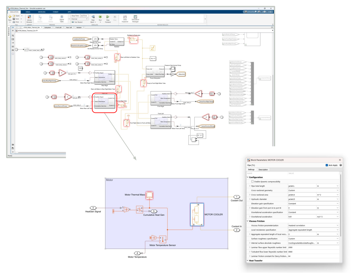
How the model works
What goes into the model
Logged race voltage and current, V(t) and I(t) [V, A]
Motor heat generation, Q̇_gen(t) [W], with electrical losses assumed to be 100% heat
Pump curve: pressure rise vs. volumetric flow, Δp_pump(V̇) [kPa vs. L/min]
Coolant properties: density ρ [kg/m³], specific heat c_p [J/(kg·K)], viscosity μ [Pa·s], conductivity k [W/(m·K)]
Radiator heat-transfer coefficient h_rad [W/(m²·K)] vs. coolant flow [kg/s] and air speed [m/s]
Jacket hydraulic diameter, D_h = 4A/P [mm]
Jacket effective flow length, L_eff [mm]
Inside the model, heat flows from the motor into the cooling jacket, gets carried off by the coolant, and leaves through the radiator to the outside air. I modeled the jacket as a Simscape pipe defined by its hydraulic diameter and effective flow length, so changing those two numbers in MATLAB let us compare jacket designs without rebuilding the Simulink model.
What the model predicts
Motor core temperature vs. time, T_core(t) [°C]
Peak motor temperature vs. the allowable limit, T_core,max [°C]
Coolant inlet and outlet temperature, T_in and T_out [°C]
Coolant mass flow rate, ṁ [kg/s]
Pressure drop across the cooling jacket, Δp_jacket [kPa]
Heat rejected to the coolant, Q̇ = ṁ · c_p · (T_out − T_in) [W]
Jacket convective heat-transfer coefficient (cooling performance), h [W/(m²·K)]
Time to thermal steady state, t_ss [min]
Validating it
The first version didn't match test data closely enough. Instead of adding complexity, I compared predictions with physical tests, found which assumptions drove the most error, and revised those. The final model had ~20% lower error against test data than the previous model, and it agreed with a separate radiator test that measured h_rad against coolant flow rate and air velocity.
Testing the jackets
I led steady-state tests on an aluminum-block motor model, measuring coolant inlet and outlet temperature [°C], motor core temperature [°C], coolant mass flow rate ṁ [kg/s], radiator inlet and outlet temperature [°C], and heater power input [W]. From those:
Q̇ = ṁ · c_p · (T_out − T_in) [W] h = Q̇ / (A · ΔT) [W/(m²·K)]
Analyzing the results in MATLAB identified a 15% more efficient jacket geometry.
More turbulence raises h, but it also raises the pressure drop across the jacket and the pump power needed, so the most turbulent design isn't automatically the best one. I also designed gyroid and cylinder-infill jacket concepts in CATIA. In CFD, the gyroid raised turbulence (Reynolds number) by about 15%, and that study fed into the team's choice of a circular-channel jacket.
Lesson: the hard part of modeling isn't building the model. It's deciding which assumptions matter and proving the model is useful for a design decision.
Tools: MATLAB, Simulink, and Simscape's thermal-liquid library for the model; CATIA and CFD for the jacket concepts.